Star Wars Celebration Europe 2023: London

An event not to be missed for any Star Wars fan, Celebration! This was/is a BIG event for me, not only because of the chance to help out again with fellow droid builders stand, putting on a display to the public, meeting and greeting fellow Star Wars fans but I also have the honour of participating in the STEAM room on the 3rd floor. For anyone who heard of this before please check out https://www.grantimaharafoundation.org/ I had the most wonderful time. Taking part in the STEAM activities was an incredible experience I will never forget and hope to do again in future.

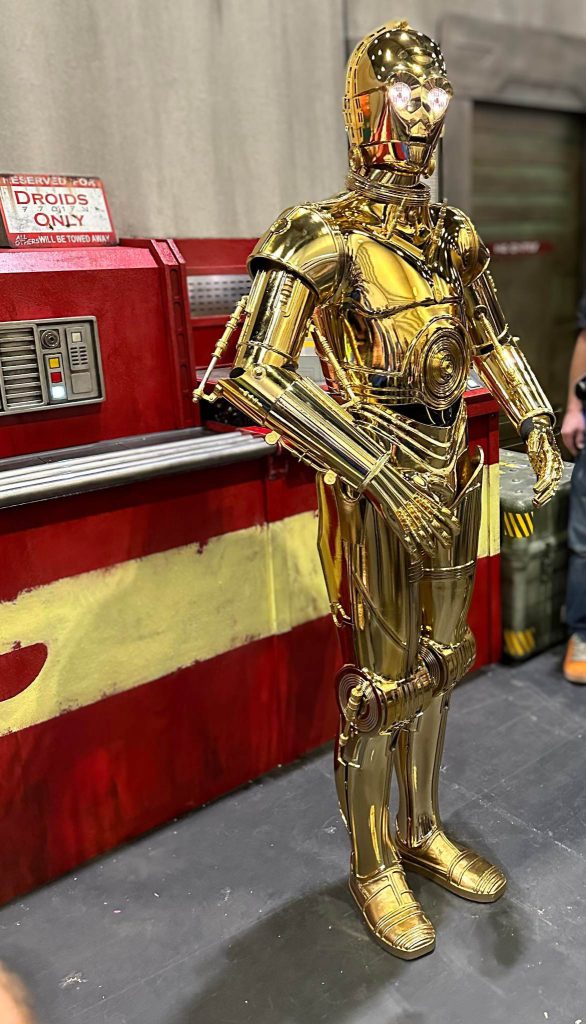
I also had the another great first experience at Celebration due to it being my first outing ‘as’ 3PO. A character I’ve enjoyed seeing on screen in all the Star Wars films over the years, portrayed brilliantly by Anthony Daniels. Some may jovially poke, it being the first droid I have officially completed but don’t get your hopes up just yet!

On average I suspect it was 45minutes to an hour to suit up and de-kit with two helpers on hand. Which if you are reading this, thank you James and Chris. I couldn’t have done it without you! It isn’t the most comfortable costume I’ve ever worn but I’m no strangers to Star Wars costumes (I also have a Biker Scout and RoTJ Fett) so I didn’t find it all that bad. The worst part for me wasn’t being bolted into the lid and unable to remove it myself but was actually the legs as I have made them just slightly too tall which pushed up the shorts. It made it very difficult to walk in. I had an extra complication that the shorts didn’t quite fit with enough room to spare in the thighs so it was like walking with splints, unable to bend and without forgiveness. A potential issue for 3PO builders using Jesse M’s files with the hope of wearing the costume. So, this is one area of attention I plan to focus on when I re-do them. At least I will have time to test fit before the next Celebration! 😉

From the Torso up I found most of the costume comfortable, not being one for crowds the helmet actual gave me some added comfort, feeling like it distanced me somewhat from so many people so it was a blessing in disguise. That said, on a hot day I am sure I won’t want to spend too long in it. The arms due to the solid brass parts were very heavy. On a good day I think this wouldn’t be an issue however I was under the weather for part of the event so struggled to stay suited up for long.

I really must start bringing out some videos as I have always intended. I am working up to it and will do reviews of parts, materials, pro’s and con’s etc.

A short clip one of the fellow builders managed to capture and edited together with some stills of my outing. Stay tuned for more updates.

Tinkering with Brass

Another night spent in the ‘workshop’ and this time making my own brass parts for 3PO. As I’d opted to upgrade the various arm pistons for brass but didn’t come with brackets I decided to use Jesse’s 3d files as a template. If you are part of the C-3PO builders group already on facebook you’ll no doubt know who I’m referring to but for those that don’t Jesse is the guy who painstakingly cadded up a very good version (and several iterations since I might add) of the 3PO suit and made it available for free, for all to download on the proviso no one starts trying to resell his files and/or rip people off – this of course is frowned upon and rightly so amongst the community because simply it doesn’t come under ‘community’.

Anyway, I printed out a few of these brackets, had them golded but they a) didnt look right and b) I didnt like the odds of them surviving a troop under the weight of the brass. Using them as a template I cut out new brackets from a sheet of brass I had spare for just such an occasion. Lucky that!

Brackets cut on the band saw, at least after I replaced the blade, I was ready to square of the edges and drill the mount holes. I marked where my limits to save re-cutting more blanks.

After cleaning each bracket up a little more with a file and sanding block I retested the fit onto the vac metalised arms and they’re ready for glue. I’ll add here a particularly useful bit of info and thats if you happen to fibreglass your own suit whether for display or wearing then add a few mm of fibreglass cloth to the inside of the bicep and follow up with a gel like layer around where the bracket would sit. This allows a third surface or face for adhesion, so you can be sure the brackets are held firmly in position.

Not bad for a first attempt I think. I was really pleased with the outcome anyway and it’s stuff like this that reminds me we are ‘builders’, we make stuff ourselves, we don’t just walk into a store and buy it off the shelf, we make, we build and honestly it’s all part of the fun.

A few people have contacted me about the brackets and said they’d like a set if possible and I’d love to help but I wouldn’t like to do a large number of these all by hand so after Star Wars Celebration I’ll be trying to organise a small CNC’d run to help people out and will then make them available here at cost. If you’re interested check back soon! Oh and see you at Celebration?!

3PO Updates

The past few days I’ve been tinkering around with some of the greeblies (random adornments) that you see on 3PO. They are solid brass made by a talented friend of mine and rather than glue some of them to the suit I opted for bolting them on where possible and reduce the risk of bits falling off and getting lost. It also allows me to remove the majority of them if the suit ever becomes damaged or if they need polishing without scratching the suit.

Above is one of the examples and on the upper greeblie I polished it up a little to show the difference in finish. It doesn’t look much but when all the brass is polished it does add a certain dynamic to the costume.

After marking out where I needed to I drilled and tapped suitable for M3 bolts. This is just what I had a lot of spares of. I was careful to measure the distance of the plunge on the pillar drill first as not to drill all the way through the brass as that would have been a disaster! Even tapping these was awkward and there isn’t much after the chroming process that doesn’t make you nervous given any bit of adding finishing touches could also result in damaging the suit.

Thankfully, all went well. The first of many brass bits to go…

C-3PO

After building astromechs a protocol droid seemed a logical choice, especially as so many fellow builders in the club kept suggesting I had the frame for it!

I must admit, I do quite like building things that you don’t see many of and its this that pulls me towards learning cad and electronics more and more amongst other skill sets. Although there is not so much a specific club, there are groups of people who have really helped and enabled me to develop my own suit.

Unlike the other droids til now, 3PO is entirely 3d printed. He’s come with his own unique challenges but it again is another journey and one which I look forward to follow for years to come.

If you are thinking of printing or building your own suit I can’t recommend the C-3PO builders group on Facebook enough. There are some very talented people out there and the kindness of some has enabled anyone with a 3d printer to jump into building their own suit.

I’ll jot down some updates again soon, so stay tuned!

#R2RND

I started my droid building journey some time back, perhaps around 2007/2008 after seeing the UK R2 Builders at a nearby event. I was immediately enamoured by what ordinary folk could achieve so close to, if not better, than an original! I realised it would be a huge undertaking and not something I could do in a day, week or month but I figured if they could then perhaps why not me?! I love making and building things and I had the most enjoyable chat with a few of the builders!

Simon, whose aluminium R2 was so silent, the foot drives were utilising a belt method opposed to chain drive! Due to this it seemed to have more response to others. As I found out in later years this isn’t just down to the ‘drives’ its also how the ESC is programmed but its surprising to see the difference of a belt driven R2 in handling and noise, more so in a quiet room.

Next up I met Brad. He was a tech guru and had the most tricked out droid (BHD). It had all the bells and whistles no doubt about it and even had the most sought after mod of all, a 2-3-2 mech! Not something he used often but amazing to see any time any where. The engineering this guy put into his droid, parts and electronics. Incredible. We had a great little talk and he really showed what can be achieved by putting the time in and not cutting corners….something which he would repeat to me every so often over the years!

Finally I came across Colin. A true gent. If I’m honest I put it down to him for all his encouragement from start to finish that kept me building. He saw my enthusiasm and suggested if I put the time in then its a very rewarding hobby and it is just that. His droid did everything he wanted it to and he went on to build some more fantastic droids.

I’d originally signed up on yahoo groups but gave it 6-12 months of research on astromech.info and astromech.net (the main builders forums) before I started my first droid, a styrene (HIPs) build and years later I’m still building and starting my own aluminium droid (R2-RND!) affectionately referred to as my R2 Research and Development droid.

So skipping forward a few years…after my first build and many events I had the opportunity to purchase someone elses work in progress. A fellow builder called Max, who was an engineer and had slowly been using information he’d gathered to build his own droid from scratch….all but the dome he’d made himself. The frame (as pictured above) for example based on documented JAG designs (another builder in the US). Max had done a great job with so much but it was still far from finished and as I found out when rebuilding things…the frame wasn’t entirely up to spec but he gave me the first foot up onto the ladder and in return he was able to pursue his new hobby – American muscle cars! I remember being a little nervous for spending so much in one go on a hobby but then he did give me a ride in his Plymouth duster which was incredible!

So R2RND continues to be a project, years on and I continue to read up on things, learn new stuff and one day I will finish him but I’m in no rush. The important thing for me is to continue enjoying what I do. I don’t have to spend every day working on something until its done, I have multiple projects on the go all the time because I like to dip in and out of them. I guess its like people enjoy reading but don’t wish to read the same book or genre all the time, sometimes they like to find something different to occupy their mind.

So anyway, there is a little back story to R2RND. I’ll keep updates coming and I’m sure you’ll see a few other projects coming up in between too.

Vintage Sewing Machine Lamp

Another birthday and so another project, once more with something of a vintage feel!

For the recipient sewing was an enjoyable past time, this gave me an idea ‘why not upcycle an old sewing machine and make it into a lamp’? I’ve seen plenty of people using old paraffin blow lamps and jamming bulbs in the ends of them which isn’t quite my cup of tea however I thought the natural shape of the sewing machine lends itself well to being an actual lamp as well as providing a quirky hidden compartment for a special message (more on that to come later)!

Before continuing I’ll mention no fully working sewing machines have been used in my project. If it works as is, I don’t see the point in breaking something that works perfectly fine for its intended use to then butcher and use as something else. So only sewing machines destined for the recycling centre have been used.

The first part of the journey was to remove the old wooden base. This was just a couple of nuts and bolts on hinges. Some of the more stubborn nuts required 10 minutes after a squirt of wd40. I then began removing the internals from the base/bed of the main casting which reduced some of the weight of the unit but the next step reduced it vastly, separating part of the horizontal arm . This sounds quite drastic but as you’ll see this is where it instantly begins to look more lamp like (and it gave me another small side project which I’ll write up at a later date).

Using a long bladed hacksaw it took me approx 15 mins to cut through the casting though I now have a handy portable band saw which would make short work of the task. I also filed down the rough edges which in future I’ll use my Dremel.

Weight reduced, it was easier to clean the unit up and polish some of the silver accents. With the arm separated I was also able to test fit an E12 bulb fitting. In keeping with the vintage vibe I bought some braided wiring with a switch rated specifically for lighting. I fed this through the main stem and wired it up. A quick test to see all was safe and working so I turned my attention to a frame. Simple pine I had kicking around, slightly/artificially aged with the use of a little heat.

I predrilled some small holes for screws as I didn’t wish to split the wood. It also ensured I didn’t go off centre and with the length of the screws used this could have easily happened. Due to the weight I think I used 3″ wood screws as well as strong wood glue to keep the frame tight around the bed. Actually the good thing about most old sewing machines is the underside of the bed tends to have its own frame from the cast, suitable to butt upto the wood. In some areas I also joined the base to the wooden frame so its not just a snug fit holding everything in position.

On the outside edge of the frame I used two screws either side, top and bottom of the frame to ensure its held together well. Thinking about the orientation of the lamp and how a sewing machine sits normally I thought it would look good on a desk however space is always a commodity and more importantly when I first came up with the design I imagined it wall mounted and it was imagining it on a wall with a tear drop shaped Edison bulb that motivated me to make it because I liked it so much, I just hoped the recipient would too! As the lamp was intended for a wall I once again insisted on using some good long screws, neatly complementing the brass heads with solid brass cup washers as the screw heads would be forward facing. The only job left to do on the frame was to apply some furniture wax.

After all this it was a case of mixing some strong epoxy to keep the bulb fitting secure. It allowed me a little down time whilst the epoxy set so I wired up the plug and checked again for any issues.

Onto the hidden compartment! To the sewing enthusiasts it wont come as a surprise that I used the slide plates around the throat plate to install a temporary birthday message inside. Initially I was going to use a copper plate and stamp it with the message but I ran out of time however its something I may do on a future lamp. I could certainly see a number of these in a room with a vintage theme as décor and as a functional piece.

Overall I’m pleased with how it turned out and the recipient of the lamp was very pleased too however my only two regrets were 1) not finishing off the message in copper and 2) not finding a way of using the balance wheel to extend and retract the main bulb unit as an additional feature. I really wanted to get those done however it took most nights over a week and a full weekend just to complete as you see here. I’ll probably produce a few more and I may make them available in the shop and yes, all will be pat tested before going on sale if they do. Keep an eye out for future updates to see what I used the off cut for!

Vintage Vibes

I had a small table that has been lingering around the house for a long time. It didn’t really fit with any of the furniture and was somewhat bland anyway. I forget even where it came from. So in an attempt to save it from the skip or recycling centre as they are known these days I figured I would at least try to come to want to keep it.

It started life as an IKEA table/night stand. Plain pine with a vintage style handle. Being flat pack furniture it was a little flimsy so I ensured that every joint was solid by applying some wood glue and screwed it back together. That done I began with distressing it a little with a wire wheel on a drill and burning it a little to darken some areas and encourage the grain to grant some more character. I’m quite fond of colour and I found a can of used paint on a shelf so I began applying it and gave it some time to dry.

I wanted to give it a worn look, to look slightly aged so avoided coating it too thick and after it dried I went back over a little with the wire wheel and some rough graded sandpaper. I was in two minds to really experiment and try some glow in the dark resin in the recesses of the grain but thought better of it.

Once I’d achieved the look I was after I started applying some furniture wax. Just plain wax. As you can see from the images I left the very top part natural as I thought the contrast was good and it would have been far too much teal to have the whole table painted in it.

So there we have it. A shabby chic (i guess) vintage vibe table stand. It’s certainly got a lot more colour than it had. Perhaps it will benefit from another wax and over time the grain will darken too which I think will improve it more. Still undecided on it but…it kept me busy for a night.

Monitoring Cont’d

Hey all! So the monitor mount progress went well. Some may recall I needed to find a way of reducing the bolt holes in the brackets. This was an easy fix with liquid metal. A two part epoxy that creates a strong bond so once it was dry I just drilled it out so now its more suited to regular screws. Just to be safe I used two spacers to ensure it wasn’t going to move.

Rather than struggle with lifting the entire thing I just lined it up roughly, bolting the top bracket only to the wall. As the rest of the unit could then slide on I was able to mark the wall with the holes in the lower bracket, remove and drill. The issue I found with drilling breeze block however is the drill wants wander where ever it wants, so I used a large punch and trusty hammer to create enough of a divot that its ‘mostly’ drilled level. Given the types of brackets I’m using and the fact the actual bracket unit is adjustable there’s a bit of play anyway for levelling so I wasn’t too fussed, I just wanted it on the wall and functional.

Plenty of room to get my hands behind and mess with the quick release mechs for the arms and if I want to take the whole lot off, its two hex grub screws! Couldn’t be simpler!

The mount brackets and tubing cost approx £15 delivered but I received the mount itself for free, with a monitor. I was donated two tv screens so for a near enough completely free project I’m pretty chuffed with how its turned out….speaking of which….here are some final pic’s for you!

As I’ve got a Chromecast set up to the one monitor alls left to do now is find a suitable place for a docking hub, keyboard and mouse so I can hook up my laptop in there.

Wall Mounts For Monitors!

Although I spend a lot of time staring at monitors I have until recently only had one in my workshop but I’ve found having Youtube channels on as background noise quite helpful not only because I learn from them but it also inspires me as well as encourages me to continue making things and gives me creative idea’s and ways of accomplishing what I want to.

So, I’ve made a change and instead of settling on just the one monitor I am instead replacing it with a mount that can hold 3. Yes 3! Now I wouldn’t have really thought I had an issue with the one but a friend kindly donated me this mount and simply I can’t say no to free stuff! It also helped him create some space too I hasten to add! However, this mount was desk mounted and because of its width its going to take up a lot of valuable workspace and having accepted it before getting it home to size up I’ve been pondering ways to wall mount it.

Due to its design (a tube system with quick release features to change the height of the monitors) its going to cause some issues though hopefully not for long. My friend also kindly gave me a free monitor he had going spare which is great as that upped my count to two displays…..although one was a tv screen – perfectly fine, I can still use this with my chromecast and watch youtube stuff on whilst working away on the other two monitors.

The obvious thought was to use some scaffolding type connectors and tubing but again my friend came in with an answer on that too and dropped me a link to a really useful site as the sources I had in mind were much too big and his site gave the added option of different diameter tubing and fixings. I chose this over actual proper office equipment basically because it was much cheaper and effective but in keeping with the slightly industrial look I’m after for the workshop.

I’ve created a small gallery below to show the progress which in short consisted of cutting up some tubing leaving enough to insert into the 90 degree mounts and wall brackets but also bring the whole unit away from the wall enough to get to quick release handles. Another great benefit of these were the each had grub screws for a perfect fit so all I had to do was tighten it all up. Next up is filling the mounting holes with liquid metal, wait for it to go off and re-drill for smaller screws (instead of the half inch bolts that they were apparently made for. Once this is done I’ll also be using large spacers to spread the tension on the wall brackets, after all it just needs to be solid when screwed to the wall. Further updates to follow

Workshop Additions

As you may have seen in previous workshop posts I’ve been busy learning to weld, making frames, creating a workspace and now I have some hefty industrial storage too!

Thanks to a kind donation I was gifted two large architect drawer units. They were located in a cellar and not being used and the owner thought I could put them to good use, they were right! With a little elbow grease and an extra pair of hands I now have a superb matching set of units creating both a fantastic work surface and ample storage that I can wheel anywhere around the workshop or place under my workbench!

Each unit holds 4 drawers the same as the above image. They measure a staggering 33″ by 47″, the width is literally half the width of my workshop so it’s complete fluke that both units now fit side on to one another with approx 20mm either side to the wall. Yes I like to mix up my measurements!

Speaking of the drawers, these were looking a little sorry for themselves. Thankfully rust was minimal, partially down to the fact they’d last been used as storage for gun spares and repairs so they had oil all over them! The cellar they came out of was actually a shelter during the war for a local village! I feel its important to keep note of these sorts of things, sometimes they may or may not be of interest to others but I find the heritage of things interesting myself. Anyway, with a good weather day I cleaned off the oil, gently sanded back any rust and then waxed each drawer followed by the units themselves.

The frame was something I drew up. These units were stacked on one another originally and one actually had a similar metal base but it was the most rusted part of the lot (luckily!) so I decided not to keep it as it was beyond saving. I say ‘not to keep it’ I of course still have it but haven’t decided what else to use it for yet! I took the height of my breakfast bar unit as that’s where I made most small projects to date and it was a good working height. I then took the height of these units, measured the extra distance needed and began cutting some steel box section, doing sanity checks with a friend who helped. I’ve really enjoyed working with box section and as it happens I have some of it spare too so watch out for more metalwork projects!

The below image doesn’t show the castors I put on these which added extra height of course, so I also took this into account when making the legs. The swivel castors were fairly heavy duty with the front facing ones having brakes and the back free wheeling.

Its a simple design but effective, allowing me to slide the units in and be held in place under gravity. There’s no welding them to the frame or drilling holes in the units to bolt to the framework. Although it could be a little difficult, if I ever wish to remove them, this way I can too. I cleaned the runners to a bare metal finish, waxed them and them to top it off greased them too so each drawers glides out nicely even when full of tools.

The worktop was an 18mm moisture resistant melamine. I was going to go with 22 but I figured this would sit better in the frame, giving a small lip on the front and back of each unit but allows me to brush off any debris either side. Forward thinking! Both units had enough top support so that the middle of the worktop would not bow under heavy load. Before dropping the worktop into place I again had used a wood glue to seal the surfaces and sides. This made it a little darker but gave it some extra protection. At some point I will likely add a thin steel plate to one as a proper tough work top area for the bigger tools to be used on.

The final touch was adding in some foam sheets to a) prevent tools from scratching the drawers and prolong their use and b) it looked good and b) I’d hoped it would hold the tools tidy and in place. It didn’t ….but it finishes the interior of them well. With that, there’s not much more to say except thank you to their donors and my friend Dave who helped with the lifting, some welding (even though he welded one bar back to front!) and all generally assisting with the build!